5-Stage Pipelined RISC-V CPU in Verilog
2026
A 5-stage pipelined CPU implementing the RISC-V RV32I instruction set, written from scratch in Verilog. Features a full datapath, hazard mitigation (forwarding, load-use stalling, branch/jump flushing).
The project is available on GitHub.
Try it: step through a real trace
Sample programs and results come from Icarus Verilog simulations, with data dumped cycle-by-cycle. Pick a scenario and step through cycles (or press Play) to watch each instruction flow through the pipeline.
Full cycle data (every wire)
Pipelining
A single-cycle CPU has to run its clock slow enough for the slowest instruction to finish end to end. Pipelining overlaps execution instead. We split our CPU into five "stages" so we can allocate different stages to different instructions. For example, while one instruction is in Execute, the next is being decoded and the one after that is being fetched. This means the clock is bounded by one stage's delay, not one whole instruction's.
Five stages: Instruction Fetch (IF), Instruction Decode (ID), Execute (EX), Memory (M), Write Back (WB). Each stage works on a different instruction every cycle; pipeline registers between stages hold state so nothing overwrites data another stage still needs.
Cycle:      1    2    3    4    5    6    7
Instr 1:    IF   ID   EX   M    WB
Instr 2:         IF   ID   EX   M    WB
Instr 3:              IF   ID   EX   M    WB
Instr 4:                   IF   ID   EX   M    WB
Architecture
Separate instruction and data memory, so a fetch and a load/store can happen in the same cycle. 25 Verilog modules, each one job:
- ALU: 32 arithmetic and logic operations (add, sub, AND, OR, XOR, shifts, set-less-than)
- Control unit: decodes each instruction and produces 18-bit control signals
- Immediate generator: extracts and sign-extends I, S, B, U, and J format immediates
- Register file: 32 x 32-bit registers with two read ports and one write port
- Instruction memory / Data memory: separate memories; dmem supports byte, half-word, and word accesses
- Pipeline registers: (IF/ID, ID/EX, EX/M, M/WB), hold state across stage boundaries
- Hazard mitigation units: forwarding, stalling, and flushing units (described below)
Hazards
Overlapping instructions means a later one can reach a stage before an earlier one has produced the value it needs which results in a hazard. Left unhandled, the pipeline uses stale values and silently produces wrong results. Hazards can come in many forms and we have different methods/units to deal with them.
Forwarding
Suppose we have two sequential instructions A and B. When instruction B needs a value instruction A just produced, B reaches Execute before A's result has made it back to the register file. One way of solving this is via forwarding, which routes the result directly from wherever it currently sits in the pipeline to where it's needed, skipping the register file entirely.
Three forwarding paths:
| Path | Source → Destination | Latency |
|---|---|---|
| MX Forward | M stage result → EX stage ALU input | 0 cycles |
| WX Forward | WB stage result → EX stage ALU input | 0 cycles |
| WM Forward | WB stage result → M stage store data | 0 cycles |
The forwarding unit is responsible for comparing the destination register of the instruction currently in M and WB against the source registers of the instruction in EX. If the registers match the forwarding unit must use the muxes in EX to bypass the stale register values and select the forwarded value. MX is checked first, and if M and WB are both writing the same destination, M takes.
With forwarding, back-to-back ALU instructions run with zero stall cycles:
add x1, x0, x0    # result available in M by cycle 4
add x2, x1, x0    # x1 forwarded from M  → no stall
add x3, x2, x0    # x2 forwarded from WB → no stall
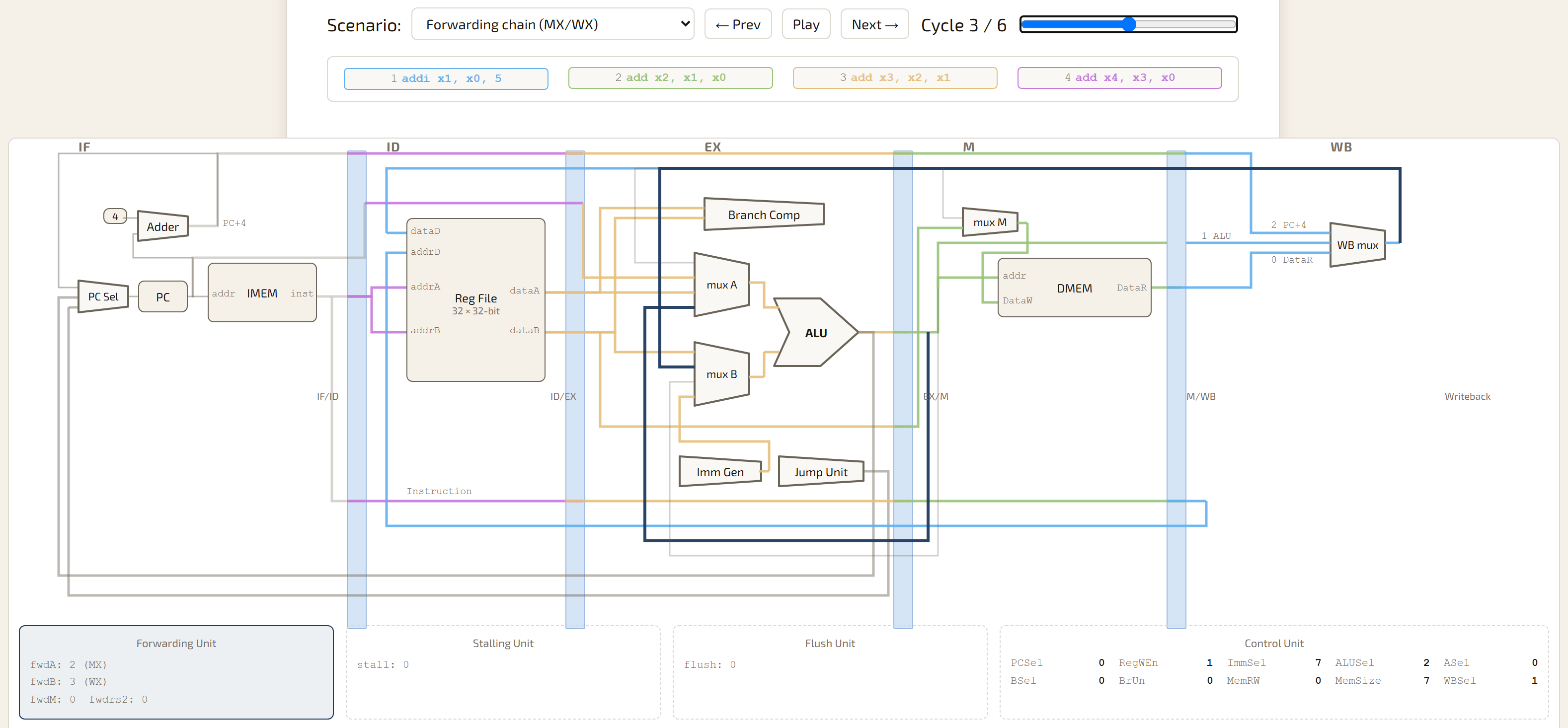
add x3, x2, x1 is in EX while x2 is still only in M and x1 only in WB — MX and WX both fire the same cycle. Try it live in the "Forwarding chain" scenario.Stalling
Load instructions (lw, lh, lb) don't have their results until data memory returns it at the end of M. If the next instruction needs that value, it hits EX while the load is still in M, one cycle too early for forwarding to reach it.
For this reason we need stalling. The stalling unit catches this and inserts a one-cycle bubble: PC and IF/ID freeze for a cycle, a NOP goes into ID/EX. After one cycle of stalling, the load can then be forwarded. The MX path is wired only from the M-stage ALU result, which for a load is the computed address, not the loaded data, so after the stall it's WX, not MX, that actually supplies the value.
Cycle:    1     2     3       4          5
lw x1:   IF    ID    EX   →  M (stall)  WB
add x3:        IF    ID   →  ID (stall) EX ← x1 forwarded from WB (WX)
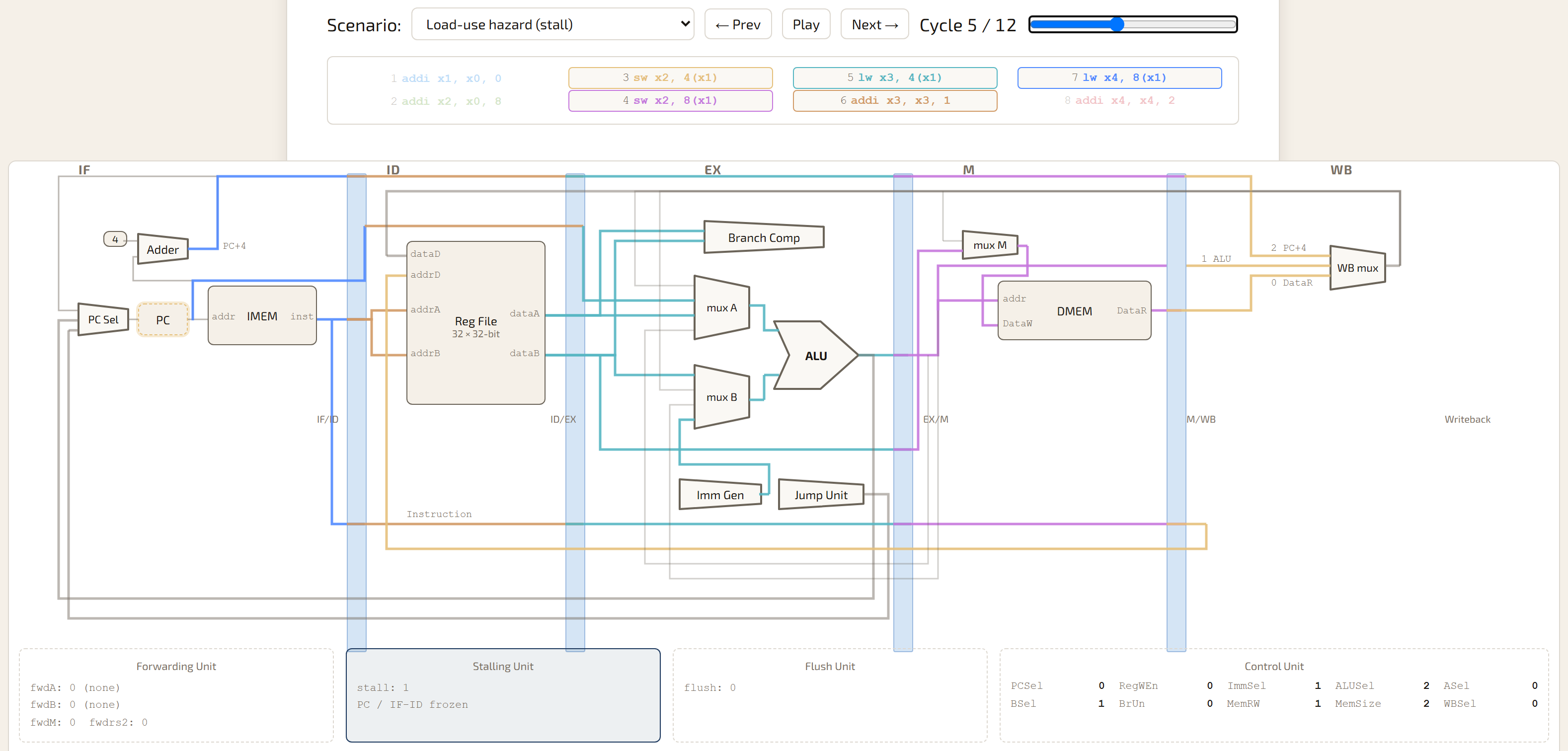
lw x3, 4(x1) is in EX computing its address — the loaded value itself isn't ready until M finishes. addi x3, x3, 1 needs that value, so PC and IF/ID both freeze (dashed outline on the PC box) and it stays in ID instead of following the load into EX. Try it live in the "Load-use hazard" scenario.Flushing
Pipelining means that we load instructions after a branch, even if the branch is taken, In the event that the branch is taken, we have to get rid of the subsequent instructions that may already be running in the pipeline. To solve this we use a flushing unit.
Branch and jump outcomes resolve in EX (cycle 3). By then two more instructions have already been fetched down the wrong path and need invalidating if the branch is taken.
The flush unit watches EX, on a taken branch or unconditional jump it replaces IF/ID's contents with a NOP and redirects PC to the target.
JAL gets special treatment, its target is PC-relative and fully computable at fetch time, so it resolves in IF with zero penalty. JALR needs a register read, so it resolves in ID at a one-cycle cost.
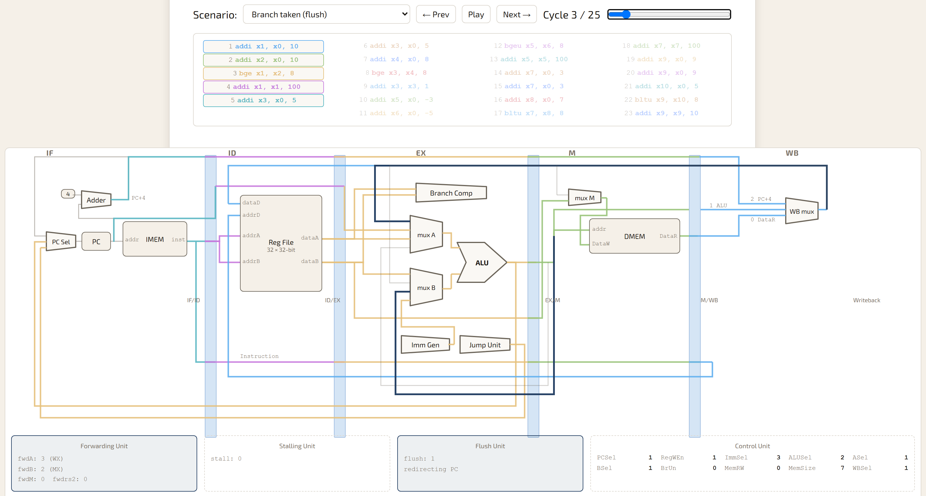
bge x1, x2, 8 resolves taken in EX. The Flush Unit fires (flush: 1, redirecting PC), and the dark PC-redirect wire carries the branch target back to PC Sel — the two instructions fetched down the wrong path get replaced with NOPs. Try it live in the "Branch taken" scenario.All possible hazards:
| Hazard | Mitigation | Penalty |
|---|---|---|
| ALU-to-ALU dependency | MX or WX forwarding | 0 cycles |
| Load followed by use | 1-cycle stall + WX forward | +1 cycle |
| Branch not taken | Static not-taken prediction | 0 cycles |
| Branch taken | Flush IF/ID, redirect PC | +2 cycles |
| JAL (unconditional jump) | Resolved in IF stage | 0 cycles |
| JALR (register-indirect jump) | Resolved in ID stage | +1 cycle |
*This CPU implements static not-taken prediction. It costs cycles on every taken branch. A real predictor would recover those cycles at the cost of real hardware and real design complexity.
Instruction Set
RV32I, the RISC-V base integer set. 37 of the ~40 core instructions tested, across all six encoding formats:
- R-type — add, sub, and, or, xor, sll, srl, sra, slt, sltu
- I-type — addi, andi, ori, xori, slli, srli, slti, lw, lh, lb, jalr
- S-type — sw, sh, sb
- B-type — beq, bne, blt, bge, bltu, bgeu
- U-type — lui, auipc
- J-type — jal
Testing
42 testbenches: 19 unit tests against individual components, 23 integration tests that run real RISC-V assembly programs through the full pipeline.
Each integration test assembles a program with the RISC-V GNU toolchain, converts it to a Verilog hex file, and loads it into simulated instruction memory. After execution the testbench reads back the register file and data memory and checks them against expected values. Tests also dump VCD waveforms for GTKWave, for stepping through a hazard signal by signal when something doesn't match.
Test build & run flow
What happens between writing an assembly program and getting a pass/fail verdict, for either CPU variant:
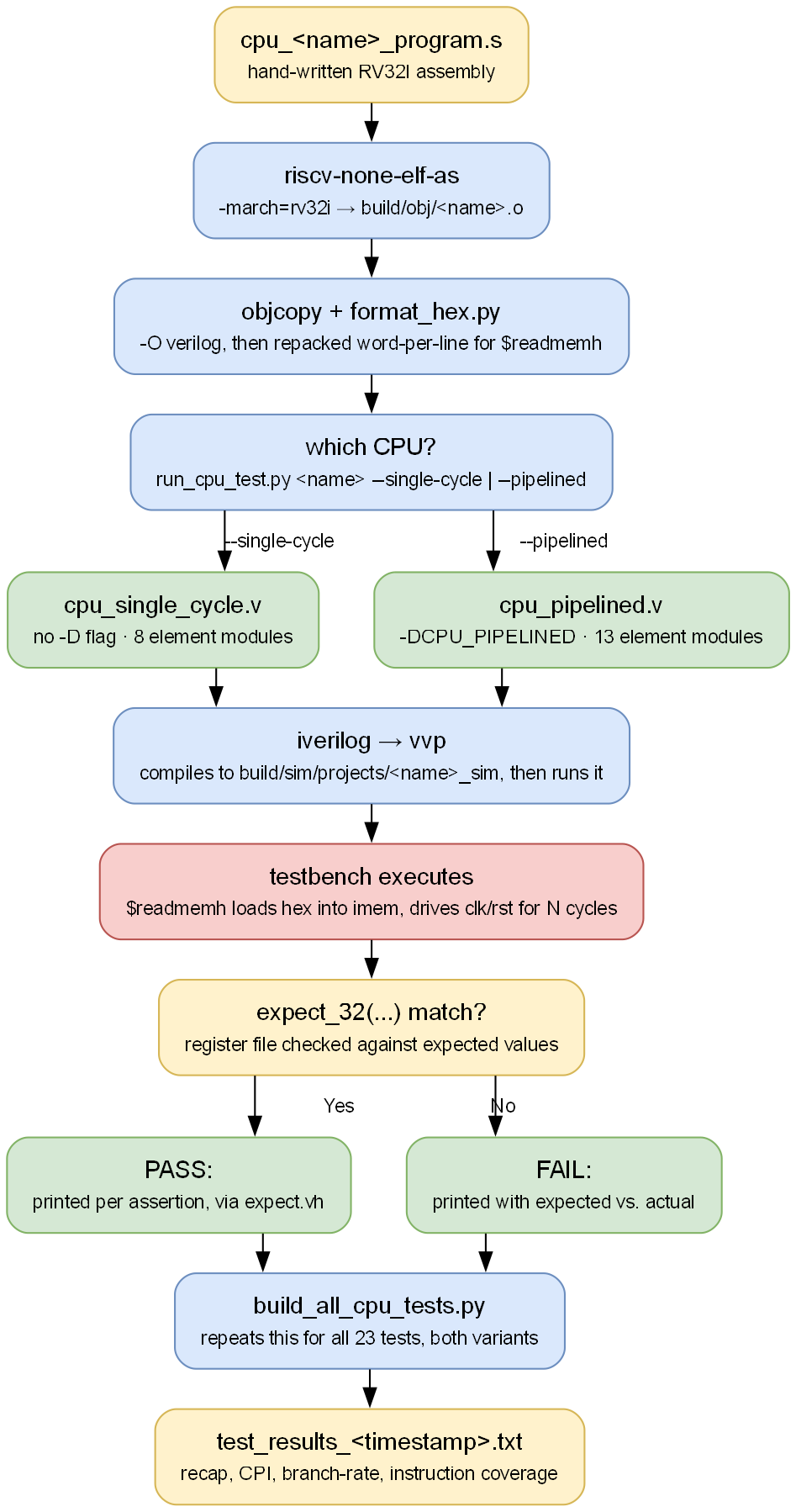
Dedicated hazard tests exercise each mitigation path in isolation:
- load_use_hazard: specifically triggers the stalling path
- branch_cmp: exercises all six branch conditions and the flush mechanism
- jal_fwd_hazard: tests JAL with forwarding-dependent operands
- store_load: exercises the WM forwarding path from WB to the M stage store port